Through the first half of 2016, British astronaut Tim Peake was aboard the ISS. During this time he carried out a number of 2m FM voice contacts with schools..
For the first few contacts, I used a Baofeng handy with a 2m whip antenna, which worked quite well for listening in, but it was not ideal. I also tried using my very basic \(\frac{1}{2}\lambda\) antenna. This didn’t seem to work much better, and I was starting to notice some pager interference coming in too.
In a bit of a hurry, I decided I should try out building the tape measure yagi I’d seen mentioned before. The idea seems to have come from WB2HOL. The next GB1SS contact was on the next day, so I made a quick trip to B&Q and got to work.
Construction
I used the nice metric guide written up by G3ZOI. I wasn’t able to get my hands on the exact parts he used, so I improvised a little.
I was building this in my university halls room, and didn’t have access to a drill, so I also built it using as few holes as possible. Those I did make were done mostly by driving a drill bit by hand! It was uncomfortable, but I was eager to get antenna built in time for the next contact.
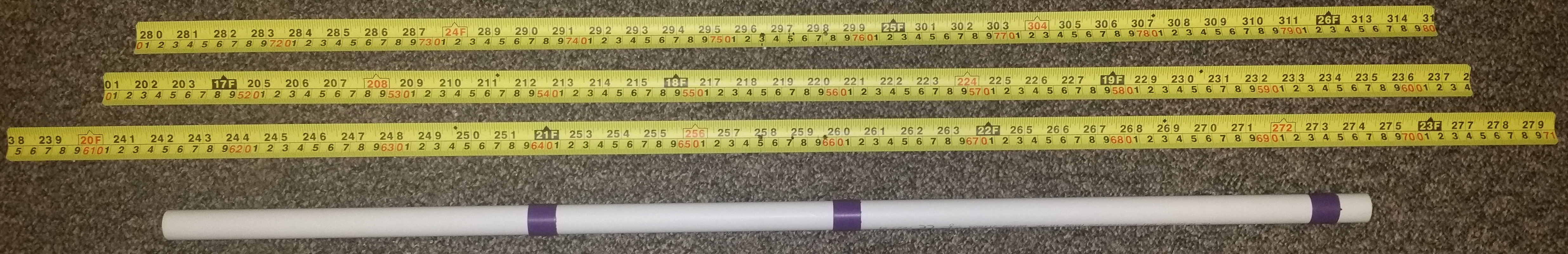
Cutting up the tape measure elements was a fairly easy task - it’s all measured out for you! A good pair of scissors, and eye protection are essential though.
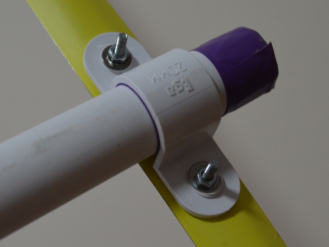
For the beam I used a section of 20mm conduit, and used conduit brackets to hold the elements to it. The clamps on their own are a fairly loose fit, so I shimmed them up with PVC tape, as seen in the next image.
The elements are clamped between the conduit brackets and a section of conduit. The section of of conduit provides plenty of friction to hold the element firmly in place.
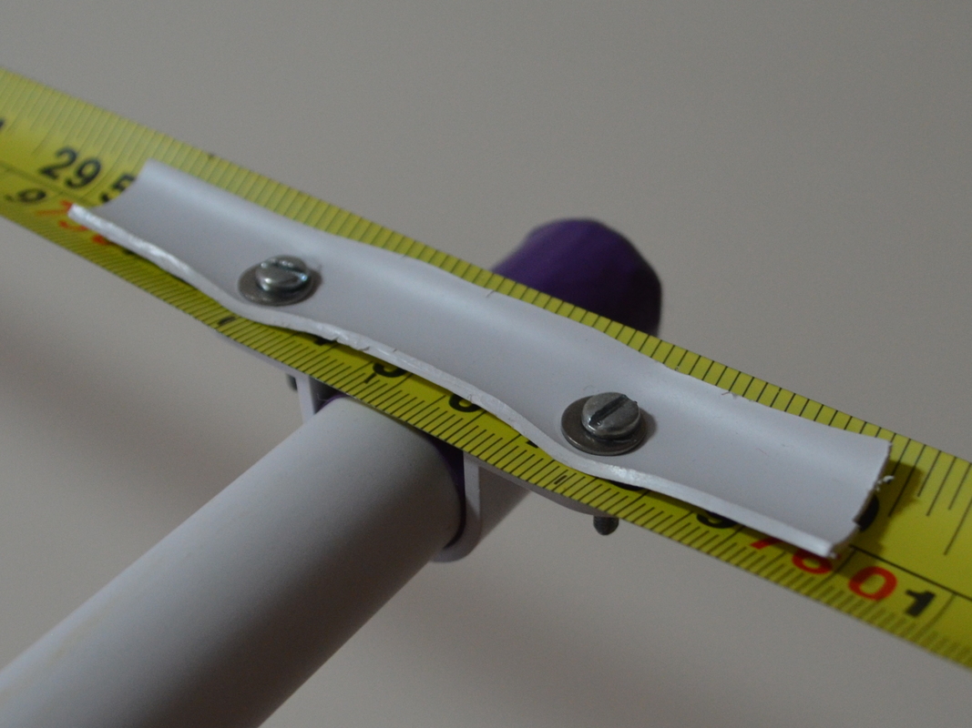
The above arrangement doesn’t work quite as well for the driven element. Because they’re only held on by one screw, the above arrangement doesn’t hold the elements steady. My solution for this was to use the wall standoff provided with the conduit brackets to hold the bracket to the beam. The two elements are then shimmed between two pieces of the conduit. The lower piece of conduit shim is just under the element section, which is why you can’t see it in the photographs.
Once the paint is sanded off, the tape measure elements solder surprisingly well with a liberal addition of flux. The coax and hairpin match can then be added. I used RG-59 because it was the only cable I had handy that I was prepared to chop up. Fortunately using 75Ω coax didn’t seem to cause too much of an issue.
Finally, 7 turns of coax were wrapped tightly around the beam, with a tight zip-tie keeping the coils tight and neat. With that the yagi is complete.
Results
The next day, I trailed the antenna on the same site I had previously operated with my handy and the whip antenna. The pass geometry was not identical, but even so I’d say there was a vast improvement. I heard close to the full 10 minutes of the contact, as opposed to the 5 or so I’d heard on previous tries.
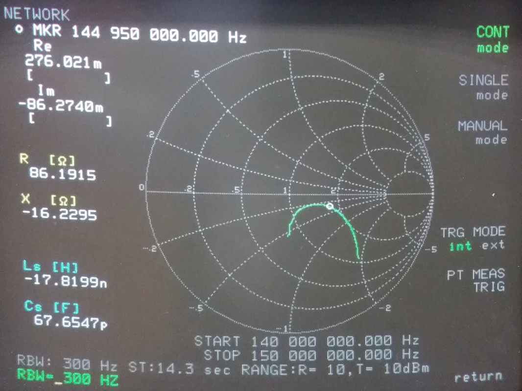
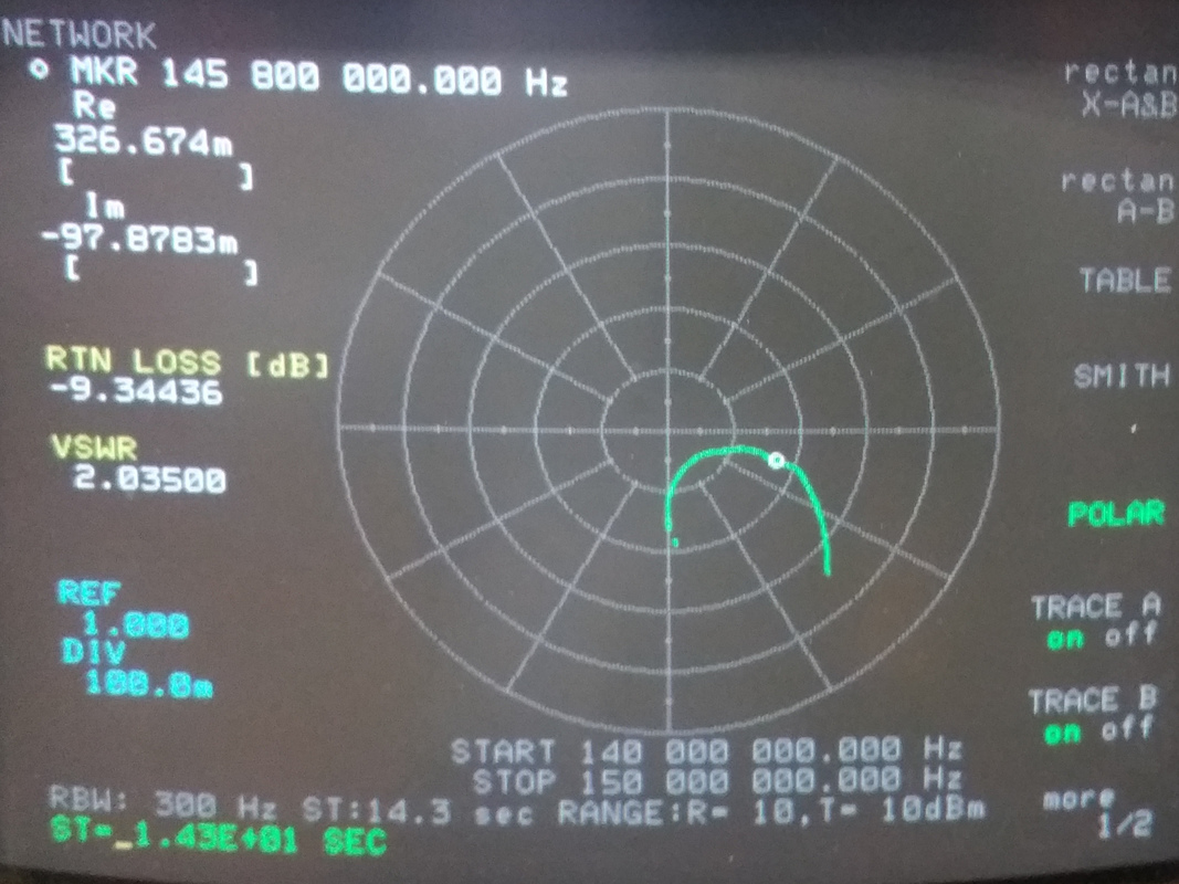
During the summer I was back at work, and able to make use of the fancy test equipment. I wheeled out the (huge!) HP4195 VNA with HP41952A test set. Together these two allow full single port network analysis. Unfortunately all this gear is well out of cal - and I didn’t have the time to work through the cal procedure with reference standards either, so these results are more qualitative than quantitative. Of course, these measurements were taken indoors near benches and lab carts, so they’ll also effect the results a fair bit.
Next year at uni I’ll hopefully have full access to some very high end RF equipment that should have calibrators and such. I look forward to testing more of my projects with this equipment. I’ll have to try this antenna on it again too, and perhaps have a shot at tuning it closer.
Overall I’m very pleased with the results so far. Perhaps one day I’ll try some ARDF and get to use the antenna for its designed purpose!